Wiring it up#
The one connection that matters#
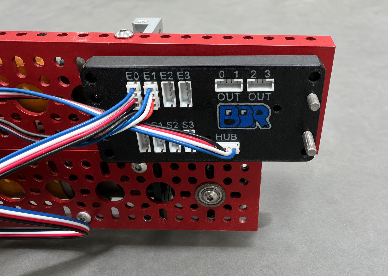
The Expander connects over a single I2C bus. That one connection carries power and data for the whole board — all four sensors included.
The board answers at 7-bit address 0x38 by default. The address jumpers move it to 0x39, 0x3A or 0x3B, which is how you put more than one Expander on the same bus.
Power#
The board is bus-powered from 3.3 V and has no regulator of its own. Total draw is around 55 mA typical — an RP2040, an IMU, the sensor mux, and colour-sensor LEDs whose current is pulsed at low duty cycle.
Nothing to do. A REV Control Hub or Expansion Hub I2C port supplies 3.3 V with 500 mA available, which is ample margin. Plug it in.
You supply the 3.3 V. Two things to watch:
- Not 5 V. There is no regulator on the board to drop it.
- Not a token 3.3 V rail. An Uno’s onboard 3.3 V pin comes from the USB interface chip and is often limited to around 50 mA, which is on the wrong side of this board’s draw once the sensor LEDs pulse. Symptoms are sensors dropping out under load rather than a clean failure. Use a proper 3.3 V regulator if you see that.
You supply the 3.3 V, and a Pi has it: header pin 1, with the regulator behind it good for far more than this board’s 55 mA.
- Not pin 2 or 4. Those are 5 V, and there is no regulator on the expander to drop it.
- Share a ground — header pin 6, or any other GND pin.
Bus pull-ups#
I2C needs pull-up resistors on SDA and SCL. The Expander does not have any on the host-facing bus, and that is deliberate: a REV Hub already provides 2.49 kΩ, and a second set in parallel would only raise sink current and buy nothing.
Nothing to do. The Hub’s pull-ups are the ones the board is designed around.
Fit your own: 2.2 kΩ to 4.7 kΩ from SDA and from SCL to 3.3 V. There are none anywhere in the system otherwise.
The internal pull-ups most Arduino cores enable in Wire.begin() are tens of kilohms — enough to look like it works on a short bench jumper at 100 kHz, and not enough at 400 kHz or over a real robot’s cable length. Intermittent reads that get worse when you lengthen the cable are the classic symptom of relying on them.
Usually nothing to do. A Raspberry Pi fits 1.8 kΩ pull-ups to 3.3 V on GPIO 2 and GPIO 3 (the SDA1/SCL1 pins), and they are the ones this board is designed around — a Hub’s are 2.49 kΩ.
That does mean the Pi’s pull-ups are the only ones in the system, so they have to carry whatever cable you hang off them. If reads get flakier as the cable gets longer, slow the bus down before adding resistors in parallel — see Troubleshooting.
Logic levels#
Every I/O pin on this board is 3.3 V and none of them are 5 V tolerant. That covers the I2C lines, the encoder inputs and the digital outputs. A 5 V signal wired directly to any of them can damage the board.
A 3.3 V host — the Control Hub, ESP32, RP2040, SAMD, STM32, Teensy 3.x and later — connects directly. A 5 V host — Uno, Nano, Mega, Leonardo — needs a level shifter on SDA and SCL, with the bus pull-ups on the 3.3 V side of it.
The same applies to what you plug into the board. REV and goBILDA encoders run off the Hub’s 3.3 V rail and are fine as they are; a 5 V encoder needs a level shifter or, at minimum, series resistors.
Sensors#
Each of the four sensor ports takes a colour or distance sensor. Plug them in before powering up — the board detects what is attached during startup and while running, but starting from a known state makes bring-up easier to debug.
You do not tell the board what kind of sensor you plugged in. It works that out.
Encoders#
Each of the four encoder channels takes a quadrature encoder (an A and a B signal). Channels can individually be switched to read a pulse-width absolute encoder instead — see Encoders.
A channel in pulse-width mode reads the A signal only. Wire your absolute encoder’s PWM output to that channel’s A line; B is ignored and can be left unconnected. Switching a channel between quadrature and pulse-width is a software setting, not a rewire — the port and the A line are the same either way, so a quadrature encoder can be swapped for an absolute one without moving the cable.
Which wire is A? Go by colour, not by letter: this board’s A and B do not follow the Control Hub’s naming, so the wire REV calls one thing is not necessarily the one we call the same thing. On REV cabling, the Expander’s A channel is the blue wire.
That matters most on a pulse-width encoder, where the PWM signal has to land on A — the blue wire — because B is never read, and a signal on the wrong line reads as no signal at all. On a quadrature encoder the two swapped just count backwards, which you can correct on the board.
If you are using the localizer, two of these channels carry the X and Y tracking pods. Which two is your choice, but note it down as you wire them — the localizer has to be told, and it will not start until both are assigned. See Which encoder ports the pods use.
Digital outputs#
You only need to wire these if you are using the standalone trigger feature, where the board watches a condition for you and reports the answer on a pin.
Each digital output connects to a digital input port on the Hub, and your match code reads it as a stock DigitalChannel. Add that input to your robot configuration with a name that says what it means — over_target reads better than dout0 in six weeks’ time.
Each digital output connects to any input pin on your board, and your sketch reads it with digitalRead(). Nothing else is needed — no library call, no configuration:
pinMode(2, INPUT);
...
if (digitalRead(2) == HIGH) { /* condition is met */ }
Each digital output connects to any GPIO input on the Pi, and your script reads it like any other input pin. Nothing else is needed — no driver call, no configuration:
from gpiozero import DigitalInputDevice

trigger = DigitalInputDevice(17)   # BCM 17, header pin 11
...
if trigger.value:
    ...  # condition is met
The expander’s outputs are 3.3 V, which is exactly what the Pi’s pins want.
If you are not using triggers, leave these unconnected.
Powering up#
The board runs its own firmware and begins working the moment it has power. It does not wait for your code, and it does not need it — if you have saved a trigger configuration to flash, the board starts enforcing it immediately at power-on, whether or not anything is talking to it.
A sanity check before you write any code#
Run the BBRSensorDumpTest OpMode. It dumps every live value the board produces — encoder counts, sensor types, colour classes, distances, and IMU state — in a single transaction. It is the fastest way to confirm your wiring is right before you start building on top of it.
See Example OpModes.
Run the DeviceInfo example. It prints the firmware version, hardware variant, capability bits, status flags and what is plugged into each sensor port. If that report appears, your wiring, pull-ups, logic levels and address jumpers are all correct.
Then run SensorDump, which dumps every live value the board produces in a single transaction.
See Example sketches.
Run python3 examples/device_info.py. It prints the firmware version, hardware variant, capability bits, status flags and the address it answered at. If that report appears, your wiring, pull-ups, logic levels and address jumpers are all correct.
Then run examples/sensor_dump.py, which dumps every live value the board produces in a single transaction.
Before either, i2cdetect -y 1 tells you whether anything is on the bus at all.
See Example scripts.