What you have#
What’s on the board#
| 4 encoder inputs | Quadrature, or pulse-width absolute |
| 4 sensor ports | Colour or distance, any mix |
| 4 digital outputs | Driven by the board itself |
| Gyro / heading | Onboard, six-axis |
| Field pose (x, y, heading) | With two dead-wheel encoders |
If a heading or pose call fails — an exception in Java, false or NAN in C++ — that means the board cannot give you a trustworthy answer: a gyro that isn’t responding, or one that hasn’t settled yet. It fails rather than returning zero on purpose. See Troubleshooting.
Ports and numbering#
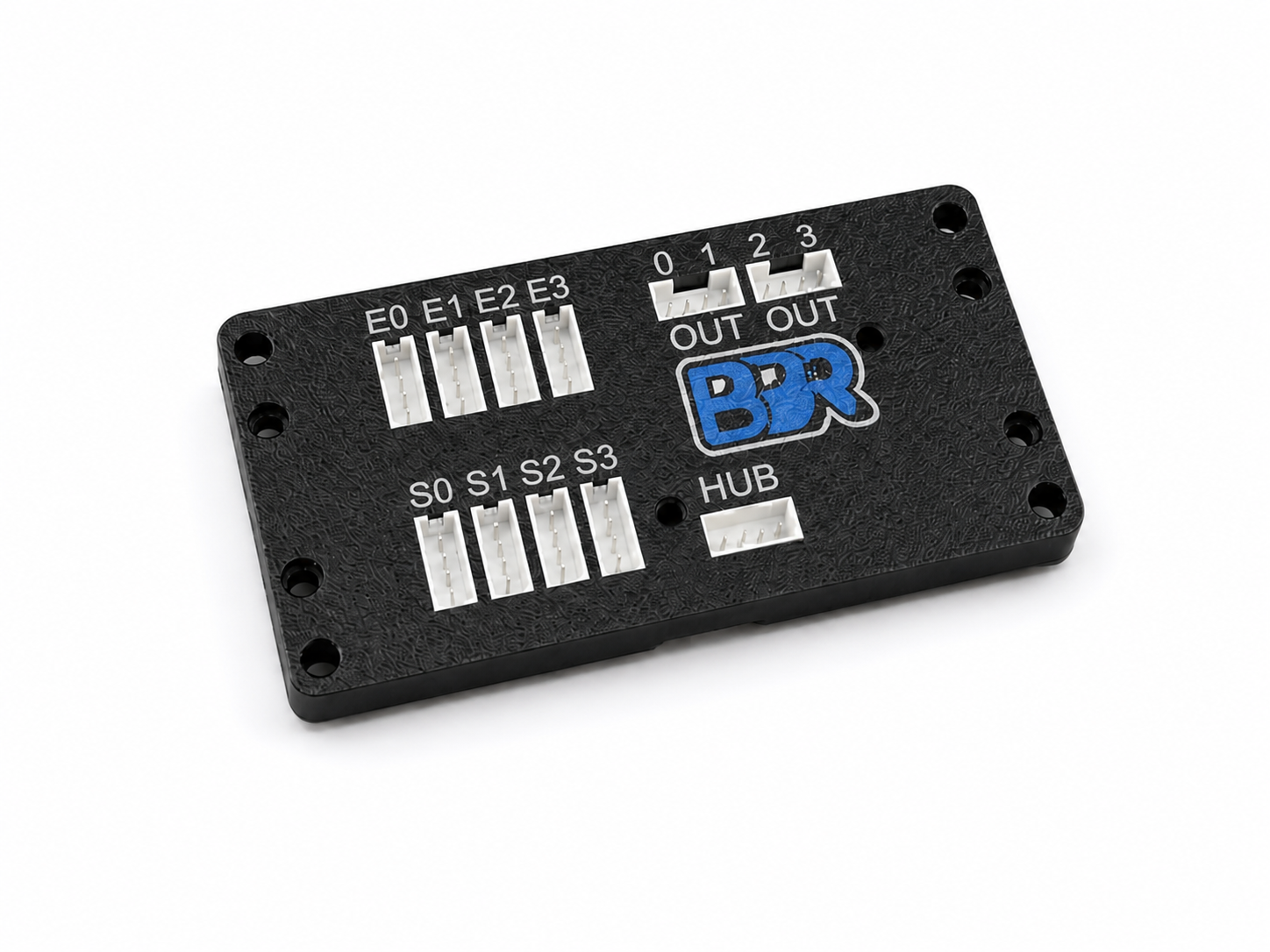
Everything is numbered 0 to 3, and each group is numbered independently:
- Encoder channels 0–3 — quadrature by default; each can be switched to read a pulse-width (PWM) absolute encoder instead. On the odometry variant, two of these carry the localizer’s tracking pods — you choose which two, and they must stay in quadrature mode. See Which encoder ports the pods use.
- Sensor ports 0–3 — each takes a colour or a distance sensor. Any mix is fine, including four of the same kind.
- Digital outputs 0–3 — driven by the board, read by the Hub as ordinary digital inputs.
Sensor port 2 has nothing to do with encoder channel 2 or digital output 2. They are separate things that happen to share a numbering scheme.
Supported sensors#
| Sensor | Kind | What you get |
|---|---|---|
| APDS-9151 | Colour | Colour classification, raw R/G/B/IR, proximity |
| VL53L0X | Distance | Range in millimetres, signal quality |
The board detects which kind of sensor is on each port by itself — there is nothing to configure. Ask it what it found:
exp.getSensorType(0);        // COLOR, DISTANCE, or EMPTY
exp.isSensorConnected(0);    // true while a sensor is detected
expander.sensorType(0);        // BBRSensorType::Color, Distance, or Empty
expander.sensorConnected(0);   // true while a sensor is detected
expander.sensor_type(0)        # SensorType.COLOR, DISTANCE, or EMPTY
expander.sensor_connected(0)   # True while a sensor is detected
Colour slots#
Each sensor port can remember up to 7 colours, numbered 1 to 7. You teach them by example — hold something in front of the sensor and tell the board “that is colour 1”.
Slot 7 is used internally by the triggerWhenNear() helper on distance ports. If you use that helper, keep your taught colours in slots 1–6 on that port so nothing collides.
The colours you teach live in the board’s flash, not in your program. They survive a power cycle, and they apply no matter what is talking to the board — teach them from an Arduino sketch and a Control Hub will read the same classifications back.
What the board needs from you#
- An I2C bus. The board appears at 7-bit address
0x38, jumper-selectable up to0x3B. - 3.3 V power, about 55 mA, over the same connection. The board has no regulator of its own.
- Bus pull-ups — which a REV Hub and a Raspberry Pi already provide and an Arduino does not. See Wiring it up.
- A digital input pin for each digital output you want to read — only if you use the standalone trigger feature.
All four sensor ports share that one I2C connection. The board handles the switching internally, so four sensors cost you one port on your host, not four.
What it does not need#
No vendor runtime, no specific host, and nothing running for the board to do its job. It is an ordinary I2C target at 100 or 400 kHz — see Choose your platform.