BBR Digital Expander#
One I2C port in. Four encoders, four sensors and four digital outputs out.
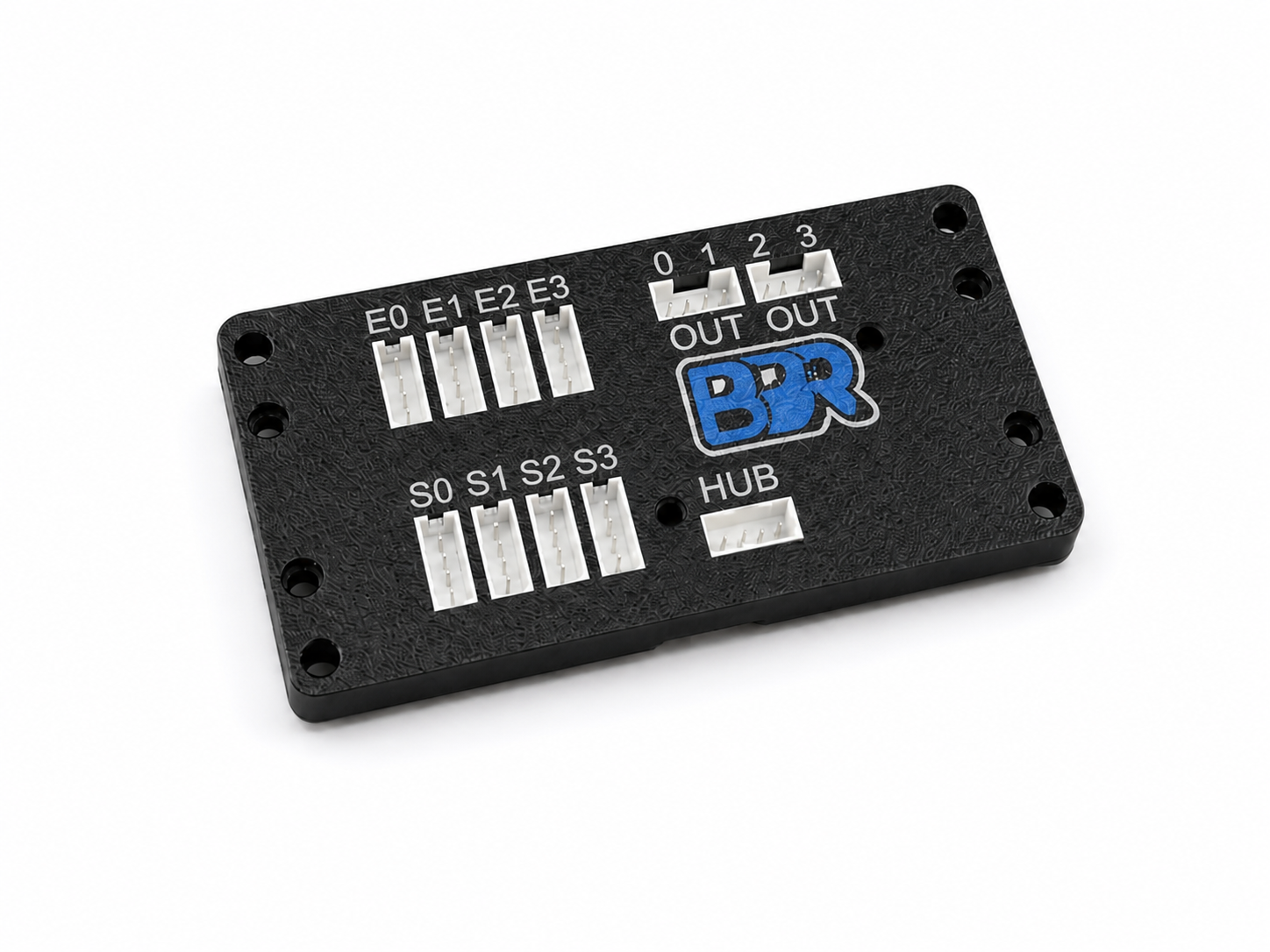
The BBR Digital Expander is an expansion board that plugs into a single I2C port and gives your robot:
- Four extra quadrature encoder inputs — with velocity calculated on the board, so you don’t have to differentiate counts yourself.
- Four sensor ports — colour or distance sensors, four of each kind if you want, all sharing the one I2C port you plugged into.
- Four digital outputs — which the board drives on its own, without your code in the loop.
- Heading and pose — from an onboard gyro and two dead-wheel encoders.
It was designed for the REV Control Hub and Expansion Hub, and that is still where most of these boards end up. But there is nothing FTC-specific inside it: it is an ordinary I2C target at 100 or 400 kHz, so an Arduino, an ESP32 or a Raspberry Pi drives it exactly as well. See Choose your platform.
Why you’d want one#
You ran out of ports. Every FTC team hits this. The Control Hub has four motor encoders and a handful of I2C buses, and by the time you have a drivetrain, a lift and an intake, the arm encoder and the colour sensor are fighting over what’s left. The Expander gives you back four encoders and four sensors for the cost of one port — and if you need more, add a second board. On a microcontroller the same arithmetic applies to pins, interrupts and timers.
Your loop got slow. Four I2C sensors read individually is four round trips every cycle. The Expander reads all of them on its own, in parallel, and hands you the answers in one transaction. Reading four sensors costs about what reading one used to.
You stopped writing the same code over and over. Every season someone rewrites “read the colour sensor, compare it to a number, decide if it’s the right sample.” The Expander does that comparison on the board, continuously, at a speed your loop cannot match — and tells you the answer as a plain true/false.
Your autonomous knows where it is. The board fuses its gyro with two dead-wheel encoders and gives you field position in millimetres, no maths homework required.
The idea#
Most sensor code on a robot follows the same shape: read a sensor every loop, compare it to a number, act on the answer. That costs you I2C traffic, loop time, and a surprising amount of code for what is usually one decision.
The Expander lets you move that decision onto the board. You teach it what to look for once, during setup, and it watches for that condition continuously at high speed. Your match code reads the answer as a plain digital input:
// Setup OpMode, run once. Ever.
exp.teachColor(0, 1);            // show it the target: that is now colour 1
exp.triggerOnColor(0, 0, 1);     // digital output 0 goes high whenever colour 1 is seen
// Match OpMode. No BBR driver, no I2C, no loop cost.
DigitalChannel overTarget = hardwareMap.get(DigitalChannel.class, "over_target");
if (overTarget.getState()) { /* ... */ }
// Setup sketch, run once. Ever.
expander.teachColor(0, 1);         // show it the target: that is now colour 1
expander.triggerOnColor(0, 0, 1);  // digital output 0 goes high whenever colour 1 is seen
// Runtime sketch. No BBR library, no I2C, no loop cost.
pinMode(2, INPUT);
if (digitalRead(2) == HIGH) { /* ... */ }
# Setup script, run once. Ever.
expander.teach_color(0, 1)         # show it the target: that is now colour 1
expander.trigger_on_color(0, 0, 1) # digital output 0 goes high whenever colour 1 is seen
# Runtime script. No BBR driver, no I2C, no loop cost.
trigger = DigitalInputDevice(17)
if trigger.value:
    ...
The configuration is stored in the board’s flash, so it survives power cycles. Once it is set up, the board keeps doing its job whether or not your code is talking to it — which also means a disconnect or a crashed program doesn’t take your sensing with it. Any of the four outputs can watch any of four things: a colour you taught it, a distance inside a range you set, an encoder passing a count, or the robot facing a heading — see Digital outputs and triggers.
You do not have to work this way. Every value is also readable directly over I2C, and plenty of teams will just use it as four more encoders and four more sensors. Both styles are supported and you can mix them.
Two tiers of API#
Both drivers are deliberately split, because a first-season programmer and a fourth-year programmer want different things from the same board.
The everyday tier is one call per question. No bitmasks, no register numbers, no tuning constants to guess at — the tuning values that matter (debounce, hysteresis, signal thresholds) are preset to values that work. If you can write a line of code, you can use the whole board.
int counts     = exp.getEncoderCount(0);
boolean isRed  = exp.seesColor(1, 1);
double mm      = exp.getDistanceMm(2);
double heading = exp.getHeading();
int32_t counts  = expander.encoderCount(0);
bool    isRed   = expander.seesColor(1, 1);
float   mm      = expander.distanceMm(2);
float   heading = expander.heading();
counts = expander.encoder_count(0)
is_red = expander.sees_color(1, 1)
mm = expander.distance_mm(2)
heading = expander.heading()
The advanced tier exposes the full register map underneath — custom colour windows, output modes, latching, pulse outputs, two-sided thresholds, localizer tuning. It is there when you outgrow the helpers, and nothing in the everyday tier prevents you from reaching for it.
Start with the everyday tier. You can always go deeper later, and nothing you write today has to be thrown away when you do.
Where to go next#
- Never used one before → What you have
- Board wired and ready → Choose your platform
- Want to see working code → Example OpModes, Example sketches or Example scripts
- Something isn’t working → Troubleshooting